使用Raspberry Pi 4B SPI_1接口 控制A5133做Basic T/RX Link(本篇使用SPI1接口,需手動驅動SPI)
前幾篇介紹都是使用Raspberry Pi的SPI_0接口,這方面的現成library較多,如WiringPi ,BCM2835這些Lib 默認的SPI接口都是使用SPI_0
若要使用Raspberry Pi的SPI1接口,就需改成使用linux底層的spidev接口與ioctl函數
首先先打開Raspberry Pi的SPI1接口
sudo nano /boot/firmware/config.txt
打開SPI1並定義CS pin腳位
dtoverlay=spi1-1cs,cs0_pin=16
存檔後重開RPI
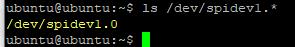
查看SPI1是否成功開啟
ls /dev/spidev1.*
表示已成功開啟SPI_1
控制A5133的邏輯與行為這邊就不再贅述,基本上就如先前說明的都是些SPI的Write/Read 操作
Demo Code:< Raspberry Pi_SPI_1 FIFO mode_0.5M_1M_2M_4Mbps_Colad9p_V0.7.zip>
P.S.:V0.7為Amiccom第0.7版Ref code抄寫過來的
因為有使用到A5133的GIO2當作RPI的輸入PIN用來判斷RF WTR狀態,因此我們一樣有include bcm2835 lib,只是用來方便判斷I/O使用
全域定義SPI的相關參數,ex:使用的SPI接口,Mode, Speed
#define SPI_DEVICE "/dev/spidev1.0"  // SPI1, CS0
#define SPI_MODE SPI_MODE_0         // SPI 模式 0
#define SPI_BITS_PER_WORD 8         // 每字傳輸 8 位元
#define SPI_SPEED 10000000            // SPI 速度 10 MHz
代碼重點說明:
P.S.請注意spi_fd需定義在main外面的全域變數 int spi_fd; // SPI 文件描述符
這邊只說明有關SPI如何驅動SPI1使RPI可以正常發出Write/Read等SPI Format
有關A5133的RF流程ex:InitRF,CalRF,TX.RXCMD都與之前的一樣
因為沒有lib,我們就必須手動定義每個SPI會用到的行為,底下說明
Ex:
Write 1 Byte==>使用在strobeCMD,只需要向A5133 發出1Byte的SPI Format
Write 2 Byte==>使用在對REG寫Value時,因為Amiccom的RF IC 寫入REG 值都是採用All in one CS,所以我們就必須要向A5133連續Write 2Byte的SPI Format
Write 9 Byte==>使用在對ID Reg連續"寫入"8Byte ID Code時,一樣All in one CS,1Byte Addr+8Byte Value=9Byte的SPI Format
Write 1 Byte Read 8Byte==>使用在對ID Reg連續"讀出"8Byte ID Code時,1Byte Addr+8Byte Value=9Byte的SPI Format
Write 1 Byte Read 1Byte==>使用在對REG"讀"Value時
Write 3 Byte==>使用在對FIFO Len REG"寫"Value時,因為A5133可以FIFO Ext to 4KByte,因此FIFO Len Reg又分High& Low Byte
Write "len" byte==>len表示任意數,使用在WriteTXData時,因為FIFO Len是可調的,因此就需要有的SPI Format是可調整Write長度內容
Write 1 Byte Read 64Byte==>使用在RxPacket();,對RXBuffer Reg讀出64Byte內容
int init_spi1(int *spi_fd);
int write_spi1_1byte(int spi_fd, uint8_t data);
int write_spi1_2bytes(int spi_fd, uint8_t *data);
int write_spi1_9bytes(int spi_fd, uint8_t *data);
int write1_read8_spi1(int spi_fd, uint8_t write_byte, uint8_t *read_data);
int write1_read1_in_cs(int spi_fd, uint8_t write_byte, uint8_t *read_byte);
int write3_spi1(int spi_fd, uint8_t *data);
int write_len_spi1(int spi_fd, uint8_t *data, size_t len);
int write1_read64_in_cs(int spi_fd, uint8_t write_byte, uint8_t *read_buffer);
基本上完成上述的所有相關SPI Format,就可以開始拼湊A5133的Code
底下說明SPI設定函數
範例1:RF_StrobeCmd函數,這裡會調用write_spi1_1byte函數,這裡指的write_byte=cmd
void RF_StrobeCmd(uint8_t cmd)
{
    uint8_t write_byte=cmd;
// 執行 1 字節寫入
    if (write_spi1_1byte(spi_fd, write_byte) != 0) {
        printf("SPI 寫入CMD失敗。\n");
    } else {
        printf("已成功向 SPI1 寫入CMD數據:0x%02X\n", write_byte);
    }
}這裡指的data=StrobeCmd函數write_byte=cmd
// 向 SPI1 寫入 1 字節的函數
int write_spi1_1byte(int spi_fd, uint8_t data) {
    uint8_t tx_buf[1] = {data};  // 傳輸緩衝區

    // 設置 SPI 傳輸結構
    struct spi_ioc_transfer spi_tr = {
        .tx_buf = (unsigned long)tx_buf,
        .rx_buf = 0,
        .len = 1,  // 1 字節寫入長度
        .speed_hz = SPI_SPEED,//定義SPI CLK速度
        .bits_per_word = SPI_BITS_PER_WORD,//定義1Word=8bit
        .delay_usecs = 0,
    };

    // 執行 1次SPI 傳輸
    int ret = ioctl(spi_fd, SPI_IOC_MESSAGE(1), &spi_tr);
    if (ret < 1) {
        perror("SPI 傳輸失敗");
        return -1;
    }

    return 0;
}範例2:Write 1 Byte Read 8Byte
這邊舉例RF_ReadID函數,這邊會調用到write1_read8_spi函數,來完成對0x06Reg做read動作,並從MISO Pin Read 8Byte的ID Code
write_byte=0x46=Read 0x06(IDCODE_REG)
read_byte預留8byte數組
void RF_ReadID(Uint8* ptr)
{
	uint8_t write_byte=IDCODE_REG | 0x40;
        uint8_t read_data[8];
	// 在同一个片选信号周期内发送 1 字节并接收 8 字节
        if (write1_read8_spi1(spi_fd, write_byte, read_data) != 0) {
        printf("SPI Read ID 失敗。\n");
        }
	else
	{
         	printf("已成功Read ID Code=");
	 	for (int i=0; i<8; i++)
		 {
          		*ptr++ =  read_data[i];
	  		 printf("0x%02X ",  read_data[i]);
	 	 }
	   printf("\n");
	}
}
write1_read8_spi1函數
tx_buf=write_byte
rx_buf=read_byte
最後記得將rx_buf第1Byte~第8Byte複製到read_data裡,因為SPI是全雙工,所以第0Byte的timing被write_byte占用,所以才會需要複製第1Byte~第8Byte
// 向 SPI1 寫入 1 字節並讀取 8 字節的函數
int write1_read8_spi1(int spi_fd, uint8_t write_byte, uint8_t *read_data) {
    uint8_t tx_buf[9] = {0};  // 傳輸緩衝區
    uint8_t rx_buf[9] = {0};  // 接收緩衝區

    // 設置要發送的 1 字節
    tx_buf[0] = write_byte;

    // 設置 SPI 傳輸結構
    struct spi_ioc_transfer spi_tr = {
        .tx_buf = (unsigned long)tx_buf,
        .rx_buf = (unsigned long)rx_buf,
        .len = 9,  // 1 字節寫入 + 8 字節讀取
        .speed_hz = SPI_SPEED,
        .bits_per_word = SPI_BITS_PER_WORD,
        .delay_usecs = 0,
    };

    // 執行 SPI 傳輸
    int ret = ioctl(spi_fd, SPI_IOC_MESSAGE(1), &spi_tr);
    if (ret < 1) {
        perror("SPI 傳輸失敗");
        return -1;
    }

    // 將接收到的數據拷貝到 read_data 中
    memcpy(read_data, &rx_buf[1], 8);
    return 0;
}
範例3:RF_ReadReg函數,這裡會調用write1_read1_in_cs函數,也就是發1byte然後Read 1 Byte Value,這用在讀取Reg數值時使用
Uint8 RF_ReadReg(Uint8 addr)
{
    uint8_t write_byte = addr | 0x40;  // 要寫入的 1 字節
    uint8_t read_byte = 0;      // 用於存儲讀取的 1 字節

    // 執行在一次 CS 片選內的 1 字節寫入和讀取
    if (write1_read1_in_cs(spi_fd, write_byte, &read_byte) != 0) {
        printf("SPI 1 字節寫入和 1 字節讀取失敗。\n");
    } else {
        printf("已成功向 SPI1 寫入 1 字節:0x%02X\n", write_byte);
        printf("已成功從 SPI1 讀取 1 字節:0x%02X\n", read_byte);
    }
    return read_byte;
}
write1_read1_in_cs
因為總SPI還是需要2Byte,因此跟之前Write1byte_Read8byte,寫法差不多,tx_buf & rx_buf都要定義2byte數組
其中tx_buf因為1byte=write_byte,另一byte沒用到就填入0x00
最後記得Return時要return rx_buf的第2字節=rx_buf[1],因為第1字節=rx_buf[0]的timing已經被tx_buf給佔用,所以要回傳時記得是回傳第2字節才對
// 在一次 CS 片選內寫入 1 字節並讀取 1 字節的函數
int write1_read1_in_cs(int spi_fd, uint8_t write_byte, uint8_t *read_byte) {
    uint8_t tx_buf[2] = {write_byte, 0x00};  // 傳輸緩衝區:第一個字節為寫入,第二個字節為讀取
    uint8_t rx_buf[2] = {0};                // 接收緩衝區

    // 設置 SPI 傳輸結構
    struct spi_ioc_transfer spi_tr = {
        .tx_buf = (unsigned long)tx_buf,
        .rx_buf = (unsigned long)rx_buf,
        .len = 2,  // 傳輸 2 字節
        .speed_hz = SPI_SPEED,
        .bits_per_word = SPI_BITS_PER_WORD,
        .delay_usecs = 0,
    };

    // 執行 SPI 傳輸
    int ret = ioctl(spi_fd, SPI_IOC_MESSAGE(1), &spi_tr);
    if (ret < 1) {
        perror("SPI 傳輸失敗");
        return -1;
    }

    // 將接收到的數據存入 read_byte
    *read_byte = rx_buf[1];
    return 0;
}
基本上掌握住這些,其他的write_spi1_2bytes,write_spi1_9bytes,write_len_spi1,write3_spi1,write1_read64_in_cs函數就都是差不多的形式
